I decided to take some time off this week to work around the house and finish things I have neglected at home.
We have one area of our yard that has underground sprinklers, but they need to be manually turned on. This is because it is difficult to get a wire to the controller – it would require a significant amount of drilling through brick and concrete.
I keep forgetting to water this part, and all the plants start to wilt – I wanted it automatic like the rest of the yard.
I could have purchased one of these…a simple timer based valve:

What fun would that be?
My only orders from the boss (wife) were “If you could get that part of the yard on the sprinkler system, that would be great.”
I had a Raspberry pi sitting around (I bought one a few months back to play with). I knew there had to be a way to use it in this project.
The PI is a small computer about the size of a pack of cigarettes. It runs Linux, and you can even hook it up to a keyboard, mouse, monitor and use it as a desktop computer.
I thought it would be a fun little project to sharpen up my Linux chops, and do something geeky over my vacation. Somehow I was going to put that Raspberry Pi in my yard, and have it control my sprinklers.
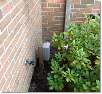
Luckily there is a outdoor power outlet right near the sprinkler valve. This would be a perfect place to put it.
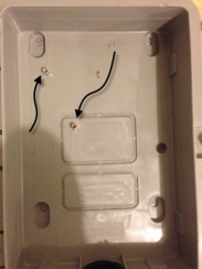
My first worry was how I could keep the rain out. I dug through my basement and found a outdoor network control box from my contracting days:

Then I took some standoffs from an old computer case, and screwed them at the right positions for the Raspberry PI board:
Later, I did the same for the other supporting boards (Relay, and power converter)
Next step..how would I switch the valve? The sprinkler valves use 24VAC and a relay would be a perfect fit for this.
I found a relay board on Amazon that is made for the PI:

Under $10 – great price.
Now I had to hook it up to my Raspberry PI. To do that I connected the IO lines to the relay inputs, and then ran the +5VDC and ground from the PI.
I had gotten this far, so I wanted to test to see if I could activate the relay.
This took a few more steps than I thought, but really it is easy.
First you need to export the interface you want to use. I was using GPIO port 4.
This is the command I used to do that:
echo “4” > /sys/class/gpio/export
Then the PI needs to know if it is for input or output.
I sent this to tell it I was going to use it for output:
echo “out” > /sys/class/gpio/gpio4/direction
Now I was ready to turn it on and off
Sending a 1 will turn it on:
echo “1” > /sys/class/gpio/gpio4/value
And a zero will turn it off:
echo “0” > /sys/class/gpio/gpio4/value
After some messing around with my wiring I finally got it to work. I could hear the relay clicking when I switched it on and off. Yea!
Hmm…but now I had a problem. I did not have a 24VAC power adapter for the valve. I would have to go buy one. I hate when that happens.
Then I remembered I had done this before.
Back in 1988 I was just a kid living at home with my parents. I had my own garden in the back yard, and needed an automated system to water the plants (Since we were about to leave for a week on Vacation). In that project I used a Commodore 64, a few transistors, and an automotive relay. The important part is I used 12 VDC to activate that sprinkler valve. The valves have not changed much over the years. That same valve back from the 80s says it requires 24VAC
So I wondered…could I use 12VCD instead for the sprinkler valve I had in my yard? I pulled a scrap power plug rated for 2A at 12VDC and put the wires across the valve. Click..I could hear the solenoid activate!
I had another reason for liking 12 volts for my supply. It would allow me to use an off the shelf cigarette lighter plug to convert that 12VDC to 5VDC that the PI needed to operate.
That was my next step. I bought a $6 USB adapter for the car:

I broke it out of its case and soldered some wires on the input and output. On the 5V side I connected a mini USB adapter…from that same plug – just really short. On the 12V side I connected some wires to share with the valve.
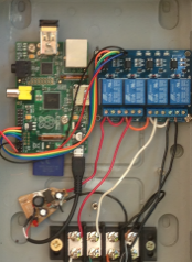
Here is what it looks like with the relays, the power converter, and the PI all put together:
The last step was to add a wireless USB. This would allow me to tinker with it from the house, and setup the schedule using a cron job.
I got this one from amazon. Another good buy – under $10. It worked right out of the box with the PI.
I mounted my box to a piece of scrap wood, and hid it behind the plants:
So far it has been working for a week now with no issues. Every once and a while I SSH into it and start poking around my Linux box running in my front yard 🙂
One more thing…Subscribe to my newsletter and get 11 free network administrator tools, plus a 30 page user guide so you can get the most out of them. Click Here to get your free tools
{ 15 comments… read them below or add one }
Great project Steve. Always wish I could do stuff like this, but my knowledge of electronics is lacking. I would probably start a fire 🙂
Thanks for sharing this. I really do want to do more of this sort of thing. Sharing your projects this is a big help to those of us trying to learn.
Thank you, I am a tinkerer, and enjoyed your blog. You did a nice job. Amazon upped the price of the wireless USB! If you have time some day, I always wanted to be able to take a picture, like the 12v setup, so that there is no background.
Also thanks for the utilities that I was able to download. Just a thought, it would have helped to know what was in the Admin Tool Kit right up front so I did not duplicate downloads
Nice article Steve – Thanks. As I’m a bit of a noobie with electronics, is it possible to add a few more detailed steps or pictures to help me build and program this. I’m really keen to build on of these.
Hi Steve. This looks exactly what I’m out to do as my first controller related pi project… I am however pretty weak on the electronics end of things and was wondering if you had a schematic of your final setup you could post. Great project and many thanks.
Hi Andrew,
I will have to pull out my info on that. It has been running out in my yard during this hard winter, and never missed a beat…so the pi turned out to be a good choice.
Can you possibly provide a larger picture of your final setup (or schematic even if basic)? I’m having trouble viewing the pic that shows how the Pi is wired to the relays. This is an awesome idea and I would like to mimic the setup but want to make sure it’s safe.
Thank you very much for sharing!
Hi Eric,
I will try to get out in the yard tomorrow to get a pic. Not sure if I can get down there since we just had 3+ inches of rain. It might be too muddy to approach the spot where it is.
I will do my best to get a really close shot.
Your biggest issue is going to be getting a stable power supply for the whole thing. My suggestion is to use one of those car USB adapters, and a 12v supply. This will allow you to get 12v for your sprinkler valves, and then a good USB power for your Pi
Hi Eric,
Here are the pics. Hopefully they are clear enough for you to see where the pins are:
Nice Stuff Steve…
One question, trying to work out how 12VDC can trigger a solenoid looking for 24VAC. I can see how the dc could look like an AC peak and perhaps the solenoid only needs momentary peak to close, or perhaps it’s integrating the 24VAC (hmmm, would half a peak integrate to 12?). But the 12VDC is not going to create anything near the 24VAC drop so I’m confused how it can make the solenoid close. Maybe the solenoid is just a lot more sensitive…
Any thoughts?
Mostly I’m curious, it looks like it
s been 2 yrs since you first implemented this. Have the solenoids stood up to getting whacked with DC over the two year period?
Finally, now add in two zones and N moisture sensors for automated on off on the zones and you’ve got a real big winner!
What is the black block with 8 screws?
Hi Rodney,
It is a junction block. That way if the wires get ripped out of the bottom of the enclosure it does not damage the circuits…it just pulls them off that block. It also makes it easier to connect.
Hi Paul,
It is still ticking. I am not sure why it works. The sprinkler solenoid may have something inside it since there are 24v and 12v systems out there…maybe they constructed it to support both.
I am amazed how well it has held up through the winters. It has been exposed to -20 F for many nights in a row and all kinds of moisture and other weather elements. The thing is still up. Last I checked it had an uptime of 500 days!
Would it be possible to run this system on a Raspberry pi zero?
I am not sure, but I don’t see why you couldn’t do it with that or even an Arduino these days. You would just need some GPIO outputs to drive the relays and code to set the times it would go on and off.